


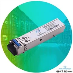


10Gb/s SFP+ 850nm Optical Transceiver Module HTSX-M8596Sx
Optic module Features
Up to 11.3Gb/s data links
850nm VCSEL laser and PIN receiver
Up to 300m on 50/125µm MMF
Hot-pluggable SFP+ footprint
Duplex LC/UPC type pluggable optical interface
Metal enclosure, for lower EMI
RoHS compliant and lead-free
Support Digital Diagnostic Monitoring interface
Single +3.3V power supply
Compliant with SFF+MSA and SFF8472
Case operating temperature
Commercial: 0 ~ +70oC
Extended: -10 ~ +80oC
Industrial: -40 ~ +85oC
Part Number Ordering Information
|
Part Number |
Data Rate (Gb/s) |
Wavelength (nm) |
Transmission Distance(m) |
Temperature (oC) (Operating Case) |
|
HTSX-M8596SC |
10.3125 |
850 |
300m MMF |
0~70 commercial |
|
HTSX-M8596SE |
10.3125 |
850 |
300m MMF |
-10~80 Extended |
|
HTSX-M8596SI |
10.3125 |
850 |
300m MMF |
-40~85 Industrial |
1. Absolute Maximum Ratings
It has to be noted that the operation in excess of any individual absolute maximum ratings might cause permanent damage to this module.
|
Parameter |
Symbol |
Min |
Max |
Unit |
Notes |
|
Storage Temperature |
TS |
-40 |
85 |
oC |
|
|
Power Supply Voltage |
VCC |
-0.5 |
3.6 |
V |
|
|
Relative Humidity (non-condensation) |
RH |
5 |
95 |
% |
|
|
Damage Threshold |
THd |
5 |
|
dBm |
|
2. Recommended Operating Conditions and Power Supply Requirements
|
Parameter |
Symbol |
Min |
Typical |
Max |
Unit |
Notes |
|
Operating Case Temperature |
TOP |
0 |
|
70 |
oC |
commercial |
|
-40 |
|
85 |
oC |
Industrial |
||
|
Power Supply Voltage |
VCC |
3.135 |
3.3 |
3.465 |
V |
|
|
Data Rate |
|
|
10.3125 |
|
Gb/s |
|
|
Control Input Voltage High |
|
2 |
|
Vcc |
V |
|
|
Control Input Voltage Low |
|
0 |
|
0.8 |
V |
|
|
Link Distance (SMF) |
D |
|
|
300 |
m |
50/125um |
3. General Description
HTF’s HTSX-M8596Sx SFP+ transceiver is designed for use in 10-Gigabit Ethernet links up to 300m over Multi-mode fiber. The module consists of 850nm VCSEL Laser, PIN and Preamplifier in a high-integrated optical sub-assembly. Digital diagnostics functions are available via a 2-wire serial interface, as specified in SFF-8472.
HTSX-M8596Sx transceivers provide a unique enhanced digital diagnostic monitoring interface, which allows real-time access to device operating parameters such as transceiver temperature, laser bias current, transmitted optical power, received optical power and transceiver supply voltage. It also defines a sophisticated system of alarm and warning flags, which alerts end-users when particular operating parameters are outside of a factory set normal range.
The SFP+ MSA defines a 256-byte memory map in EEPROM that is accessible over a 2-wire serial interface at the 8 bit address 1010000X (A0h). The digital diagnostic monitoring interface makes use of the 8 bit address 1010001X (A2h), so the originally defined serial ID memory map remains unchanged.
4. Pin Assignment and Pin Description
|

|
Pin |
Symbol |
Name/Description |
Notes |
|
1 |
VEET |
Transmitter Ground (Common with Receiver Ground) |
1 |
|
2 |
TFAULT |
Transmitter Fault. |
2 |
|
3 |
TDIS |
Transmitter Disable. Laser output disabled on high or open. |
3 |
|
4 |
SDA |
2-wire Serial Interface Data Line |
4 |
|
5 |
SCL |
2-wire Serial Interface Clock Line |
4 |
|
6 |
MOD_ABS |
Module Absent. Grounded within the module |
4 |
|
7 |
RS0 |
Rate Select 0 |
5 |
|
8 |
LOS |
Loss of Signal indication. Logic 0 indicates normal operation. |
6 |
|
9 |
RS1 |
No connection required |
|
|
10 |
VEER |
Receiver Ground (Common with Transmitter Ground) |
1 |
|
11 |
VEER |
Receiver Ground (Common with Transmitter Ground) |
1 |
|
12 |
RD- |
Receiver Inverted DATA out. AC Coupled |
|
|
13 |
RD+ |
Receiver Non-inverted DATA out. AC Coupled |
|
|
14 |
VEER |
Receiver Ground (Common with Transmitter Ground) |
1 |
|
15 |
VCCR |
Receiver Power Supply |
|
|
16 |
VCCT |
Transmitter Power Supply |
|
|
17 |
VEET |
Transmitter Ground (Common with Receiver Ground) |
1 |
|
18 |
TD+ |
Transmitter Non-Inverted DATA in. AC Coupled. |
|
|
19 |
TD- |
Transmitter Inverted DATA in. AC Coupled. |
|
|
20 |
VEET |
Transmitter Ground (Common with Receiver Ground) |
1 |
Notes:
1. Circuit ground is internally isolated from chassis ground.
2. TFAULT is an open collector/drain output, which should be pulled up with a 4.7kΩ– 10 kΩ resistor on the host board if intended for use. Pull up voltage should be between 2.0V to Vcc + 0.3V.A high output indicates a transmitter fault caused by either the TX bias current or the TX output power exceeding the preset alarm thresholds. A low output indicates normal operation. In the low state, the output is pulled to <0.8V.
3. Laser output disabled on TDIS >2.0V or open, enabled on TDIS <0.8V.
4. Should be pulled up with 4.7kΩ- 10kΩ on host board to a voltage between 2.0V and 3.6V. MOD_ABS pulls line low to indicate module is plugged in.
5. Internally pulled down per SFF-8431 Rev 4.1.
6. LOS is open collector output. It should be pulled up with 4.7kΩ – 10kΩ on host board to a voltage between 2.0V and 3.6V. Logic 0 indicates normal operation; logic 1 indicates loss of signal.

Hot Tags: sophos itfztchxf sfp+ 10g sr compatible optic transceiver, China, manufacturers, suppliers, factory, customized, buy, price, bulk, compatible brand, 10G Multi Protocol Tunable DWDM 80km SFP , 10G SFP 10km LR BIDI, 10G SFP BIDI 40km in stock, 10Gbs 10km CWDM SFP LR Transceiver Module, Duplex LC 10G DWDM 40KM SFP, 10G SFP 1310nm 2km


