


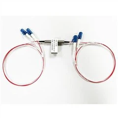


The splitter (that is, the optical splitter) is a connecting device of multiple input terminals and output terminals. It can realize the coupling, branching and distribution of optical signals in optical network system, and is the most important part of optical fiber link. M×N is commonly used to indicate that a spectrometer has M input terminals and N output terminals. Currently, the spectroscopes used in today's networking are generally 1×2 and 1×4 spectroscopes. Do you know what the light attenuation of the spectrometer is? How to choose a spectrometer? How to use the spectrometer?
What is the light attenuation of the spectrometer? How do you calculate that?
The four common technical indexes of the spectrometer are wavelength, insertion loss, additional loss and ratio of the spectrometer. In fact, the most important indicator of the spectrometer is the different light attenuation produced by the spectrometer under a specific light ratio, under the condition of different light attenuation; the spectrometer will not be different. Then how to calculate the optical attenuation of the spectrometer? Optical attenuation value of spectrometer = transmitting optical power + additional loss + insertion loss + bare fiber loss.
1. Spectrometer ratio calculation
Formula: ki = Pi/SP * 100%
Pi is the required driving power of each optical link, and SP is the sum of the required driving power of each optical link carried by the laser.
Note: In actual use, the spectral ratio has been indicated, such as 80%: 20% or 70%: 30%; One third is 70%: 15%: 15%; One quarter is 70%: 10%: 10%: 10%.
2. Calculation of additional losses
In the actual operation, the additional loss value can be measured, and the numerical detection and recording only need to be carried out according to certain operation specifications, so as to classify different links.
Generally, the loss of 1×N single-mode standard spectrometer is as follows:
Branch number | 2 | 3 | 4 | 5 | 6 | 7 | 8 | 9 | 10 | 11 | 12 | 16 |
Additional loss /dB | 0.2 | 0.3 | 0.4 | 0.45 | 0.5 | 0.55 | 0.6 | 0.7 | 0.8 | 0.8 | 1.0 | 1.2 |
3. Calculation of insertion loss
Formula: IL = -10lg (Po/Pi)
Po is the optical power at the output and Pi is the optical power at the input.
Note: In the formula, Po/Pi is equivalent to the spectral ratio of the spectrometer, i.e. IL = -10lg (KI). For example, there is a divisor, for the light of two eighth, that is, the spectral ratio of 20%: 80%. The theoretical value of the 20% spectral link insertion loss is -10lg (20%), which is approximately equal to 6.99dB.
4. Calculation of bare fiber loss
In practice, this value does not need to be calculated, and there are certain reference standards. In order to determine the final loss value, the loss value of different wavelength should be measured with strict reference to the numerical standard.
Wavelength | fiber attenuation coefficient (reference value) |
1310 nm | 0.3 ~ 0.4 dB/km |
1550 nm | 0.15 ~ 0.25 dB/km |
850 nm | 3.75 dB/km |
Note: Active connectors decay: generally 0.5dB per connector.