


What is insertion loss?
Insertion Loss usually referred to as IL, which mainly refers to the measurement of light loss between two fixed points in an optical fiber. It can be understood as the loss of optical power caused by the intervention of optical devices in the optical fiber link of the optical communication system, and the unit is dB.
What is return loss?
When an optical fiber signal enters or leaves an optical component (such as an optical fiber connector), the discontinuity and impedance mismatch will cause reflection or return, and the power loss of the reflected or returned signal is the return loss, Return Loss ( Referred to as RL). Insertion loss is mainly to measure the resulting signal value when the optical link encounters loss, while return loss is the measurement of the reflected signal loss value when the optical link encounters component access.
What are the influencing factors?
1. End face quality and cleanliness
Fiber end surface defects (scratches, pits, cracks) and particle contamination will directly affect the performance of the connector, resulting in poor IL/RL. Even the tiny dust particles on the 5-micron single-mode fiber core may eventually block the optical signal, resulting in signal loss.
2. Fiber break, poor insertion
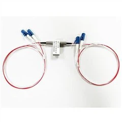
Sometimes even though the optical fiber is broken, it can still guide the light through. In this case, it will also lead to bad IL or RL. As in the picture mentioned at the beginning of the article, the APC connector is connected to the PC connector. One is an oblique 8° angle, and the other is a micro-curved grinding angle. Light may pass through the two in a short time. But at the same time, it will also cause a large insertion loss and a very low return loss, and it may also cause the two fiber end faces to be unable to be precisely connected and the light cannot pass normally.
3. Over bending radius
The optical fiber can be bent, but too much bending can also cause a significant increase in optical loss, or it may directly cause damage. Therefore, in the case where the fiber needs to be coiled, it is recommended to keep the radius as large as possible. The general recommendation is not to exceed 10 times the diameter of the jacket. Therefore, for a jumper with a jacket of 2mm, the maximum bending radius is 20mm.
Shenzhen htfuture Co., Ltd is a professional supplier of fiber optic products and WDM systematic solution. Was built by a team who has more than 10-year experiences in optical communication product R&D, fiber solution, component developing and manufacturing.