


What is fiber dispersion?
Different frequency components or different mode components of optical signal (pulse) transmitted in optical fiber propagate at different speeds, and signal distortion (pulse broadening) will inevitably occur after reaching a certain distance. This phenomenon is called dispersion or dispersion of optical fiber. The optical signal transmitted in optical fiber has a certain spectrum width, that is to say, the optical signal has many different frequency components. At the same time, in the multimode fiber, the optical signal may be composed of several modes, that is to say, each frequency component may also be composed of several mode components.
Optical fiber dispersion refers to the signal distortion caused by different frequency components and different mode components with different transmission speed. In digital optical fiber communication system, dispersion broadens the optical pulse. When the dispersion is serious, the optical pulses will overlap each other, causing inter symbol interference and increasing the bit error rate. Therefore, the dispersion of optical fiber not only affects the transmission capacity of optical fiber, but also limits the relay distance of optical fiber communication system.
When the light propagates in the optical fiber, because its frequency is not a single frequency, the working mode is not a single working mode, so the propagation speed is slightly different, which is called dispersion. If the modulated wave is a digital pulse, the width of the demodulated signal will be expanded, which will cause bit error and restrict the improvement of transmission rate. When the modulation waveform is an analog signal, the level after detection decreases with the increase of signal frequency, which shows nonlinear distortion and increases the harmonic component of fundamental wave. The transmission of CATV signal in optical fiber network causes the deterioration of CSO and CTB indexes. These phenomena are called dispersion characteristics of optical fiber, and the dispersion characteristics of the latter are also called bandwidth characteristics (or frequency characteristics).
Fiber dispersion shows a propagation state of the input signal in the fiber, which refers to the signal distortion caused by different frequency components or different mode components of the optical signal propagating at different speeds. It mainly includes intermodal dispersion, chromatic dispersion and polarization mode dispersion.
Intermodal dispersion
Intermodal dispersion is a kind of signal distortion mechanism in multimode fibers and other waveguides. In the multimode fiber, the light rays entering the fiber at different incident angles are defined as a path or a mode. Due to the different transmission path of each mode, the transmission speed (group speed) is also different, so the time difference of signal transmission between modes to the optical fiber terminal occurs. In general, some light rays will pass directly through the core (axial mode), while others will reflect back and forth between the cladding / core boundaries and propagate along the zigzag waveguide, as shown in the step index multimode fiber in the figure below. The fact is that once the light is refracted, intermodal dispersion / mode dispersion occurs. There is a positive correlation between the IMD and the transmission path. That is to say, the IMD caused by the higher-order mode (the path is longer when the ray enters at a larger angle) is higher than that caused by the lower order mode (the path is shorter when the ray enters at a smaller angle).

Multimode fiber can accommodate up to 17 modes of light propagation at the same time, and its inter mode dispersion is much higher than that of single-mode fiber. This is because the single mode fiber has a single propagation mode, that is, the light propagates along the core (axial mode) without reflecting to the cladding boundary, so there is no inter mode dispersion.
However, the situation is different if graded index multimode fiber is used. Although the light also propagates in different modes, due to the uneven refractive index of the core, the light path is no longer a straight line but a curve, and the propagation speed of the light also changes. Therefore, the inter mode dispersion can be greatly reduced by selecting the appropriate refractive index distribution.
Chromatic dispersion
Chromatic dispersion refers to the phenomenon of optical pulse broadening caused by different group velocities of different wavelength components in optical fiber, including material dispersion and waveguide dispersion.
Material dispersion is caused by the wavelength dependence of refractive index on core material, while waveguide dispersion is caused by the dependence of mode propagation constant on fiber parameters (core radius, refractive index difference between core and cladding) and signal wavelength. At certain frequencies, the material dispersion and the waveguide dispersion can cancel each other to obtain a wavelength close to zero chromatic dispersion.
In fact, chromatic dispersion is not always unfavourable. Light propagates at different speeds in different wavelengths or materials, resulting in the broadening or compression of light pulses in the fiber, which makes it possible to customize the refractive index profile to produce fibers for different purposes. G. 652 fiber is an example.
Polarization mode dispersion
Polarization mode dispersion (PMD) reflects the polarization dependence of light wave propagation in optical fiber. There are two polarization modes perpendicular to each other in the actual optical fiber. Ideally, the two polarization modes should have the same light wave propagation characteristics, but generally speaking, there are slight differences in different polarization modes. This is due to the change or disturbance of temperature, pressure and other factors in the propagation process, resulting in different transmission speed of the two polarization modes, resulting in delay and polarization mode dispersion.
How to compensate dispersion?
Although fiber dispersion does not weaken the signal, it shortens the propagation distance of the signal inside the fiber and causes signal distortion. For example, the 1 nanosecond optical pulse at the transmitter will be broadened to 10 nanoseconds at the receiver, resulting in the signal cannot be received and decoded normally. Therefore, it is very important to reduce fiber dispersion or compensate dispersion in DWDM and other long-distance transmission systems. The following will introduce three commonly used dispersion compensation strategies and methods.
Dispersion compensation fiber
By using dispersion compensation fiber (DCF) technology, negative dispersion fiber can be added to conventional fiber. Compared with the dispersion compensation fiber, the dispersion value of conventional fiber is very large and the dispersion is positive, which makes the light distribution in this kind of fiber reduce or even disappear. By adding a negative dispersion compensation fiber to it, the total dispersion of the whole fiber line can be approximately zero, so as to achieve high speed, large capacity and long distance communication. There are three compensation mechanisms in dispersion compensation fiber, including pre compensation, post compensation and symmetric compensation. Dispersion compensated fiber is widely used in the upgrading of 1310 nm fiber link, which makes it run at 1550 nm.
Fiber Bragg grating
Fiber Bragg grating (FBG) is a kind of reflective device composed of fiber, which can modulate the core refractive index within a certain distance. In the 100 km transmission system, the dispersion effect can be significantly reduced by using this device. When the beam passes through the fiber Bragg grating, the wavelength meeting the modulation conditions will reflect, and the rest of the wavelength will continue to pass through the fiber Bragg grating along the fiber. Using fiber Bragg grating for dispersion compensation has great advantages, because fiber Bragg grating can be integrated with other passive fiber devices with low insertion loss and low cost. In addition, fiber Bragg grating can be used not only as dispersion compensation filter, but also as sensor, wavelength stabilizer of pump laser and narrow band wavelength division multiplexing add / subtract filter.
Electronic dispersion compensation
Electronic dispersion compensation (EDC) is a method of dispersion compensation in optical communication links by using electronic filtering (also known as equalization), that is, filtering in the communication channel to compensate the signal attenuation caused by the transmission medium. Electronic dispersion compensation is usually realized by transverse filter, whose output is the weighted sum of a series of delay inputs. It can automatically adjust the filter weight according to the characteristics of the received signal, that is, adaptive. Electronic dispersion compensation can be used in single-mode fiber system and multi-mode fiber system. In addition, it can be combined with other functions for 10Gbit / S receiver IC. It can significantly reduce the transmitter cost of single-mode fiber system, and also increase the transmission distance of multi-mode fiber system with less receiver cost loss.
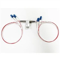
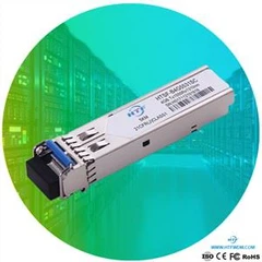
HTF's products quality is guaranteed, and the accessories are imported.
Contact: support@htfuture.com
Skype :sales5_ 1909,WeChat :16635025029