


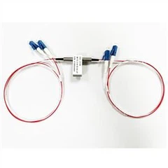
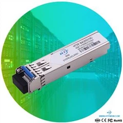


Optical module is composed of optoelectronic devices, functional circuits and optical interfaces. Optoelectronic devices include two parts: transmitting and receiving.
In short, the function of the optical module is to convert the electrical signal into optical signal at the sending end, and then convert the optical signal into the electrical signal at the receiving end after the optical fiber transmission.

How to judge the common faults of optical module?
Analysis of common fault causes of optical module for optical module (optical fiber module), its function failure is divided into transmitter failure and receiver failure, the most common problems are concentrated in the following aspects:
1. The optical module is damaged by ESD, namely "electrostatic discharge". Static electricity can cause dust adsorption, change the impedance between lines, and affect the function and life of the optical module of SFP. For example, dry environment, illegal operation, no grounding of active optical fiber equipment or poor grounding can cause ESD damage.
2. The optical port of optical module is polluted and damaged, which leads to the increase of optical link loss, so that the optical fiber link is not connected.
3. The long-term exposure of the optical port to the environment causes dust to enter and pollute, the end face of the optical fiber connected with the module is polluted, and the end face of the optical connector of the tail fiber is improperly used, which will cause the light to be polluted.
Standards for judging the quality of optical modules:
1. The optical module shall comply with MSA multi-source protocol, and the manufacturer shall pass the CE, ROHS, FCC certification, etc. among them, the multi-source protocol (MSA) standard specifies the interface and size of the module. The module manufacturer can provide the optical module with the same brand function as the switch according to this protocol, and ensure that the optical module can accommodate a variety of original equipment.
2. The optical module should have DOM / DDM function, so that users can monitor the real-time parameters of the optical module. The specific parameters include working temperature, working voltage, working current, transmitting and receiving optical power, etc. in addition, it can display the factory information of the module and prompt alarm / warning.
3. Before the optical module leaves the factory, it is necessary to carry out the real machine compatibility test to ensure that the optical module has good quality, performance and compatibility, avoid network interruption, and save maintenance time and cost. It is recommended to ask the supplier before purchasing the optical module.
4. Check whether the surface of the module is damaged, whether the golden finger has scratches, etc. if there is obvious damage, it indicates that the light module may be defective or second-hand goods.
5. According to the after-sales service, the service life of general optical modules is about 3 years, so we choose optical module suppliers with quality assurance when selecting optical modules, and optical modules produced by professional optical module manufacturers of Yitian optical communication provide 3-year warranty.
6. Use the optical power detector to test whether its optical power is consistent with the parameters in the data manual. If the difference is too large, it is a second-hand optical module.


What are the common problems of optical module in use?
1. Compatibility problems, the reasons for this situation are as follows:
a. Errors occurred in the process of importing compatible codes;
b. The software update of the device results in the failure of the original compatible code which has not been upgraded;
c. Coding error;
2. There are several reasons for this situation:
a. The electronic function circuit of optical module and equipment does not match;
b. The main chip does not match with the device;
c. Physical circuit failure;
d. Equipment failure;
e. The route information is wrong;
The method of judging the fault of optical module
1. Look at the appearance by visual inspection
The appearance of the light module is observed by visual inspection, and the surface of the module is checked for obvious damage traces. Then, the components are checked for signs of cracking, missing paste, tin connection or even burning black.
2. Comparison method to measure parameters to see the difference
If the visual inspection method looks good, you can use the relevant detection instrument to detect a new module and the module that may have a fault, and it can be divided into two situations: power on and power off. Check the voltage, resistance and waveform of circuit parts or components, and then compare the test results of new module and bad module to determine the problem.
3. Replacement method to replace components to see parameter changes
If it is found that there are differences in the introduction of test parameters, the corresponding components or components of the module that may be faulty can be replaced with good product components or components of the same model, and then test the parameters again to see whether they return to normal.
4. Determine the faulty circuit area according to some bad condition
According to some bad conditions, determine the fault circuit area, such as: poor optical power, mainly check the transmitting area, poor sensitivity, check the receiving area, etc., which can reduce the maintenance time and improve the efficiency.
5. Through the structure of the hanging light module, the components of the fault can be judged
We all know that the optical module is mainly composed of Tosa module, Rosa component and PCBA board. If you want to judge the components of fault, there are several methods to judge:
① Remove Tosa and Rosa components, and test their performance on the component test board.
② When the power is on, use a multimeter to measure the voltage of each pin to see whether the voltage value is normal; when the power is off, use the multimeter to test whether the circuit led out by the heel pin of the pin is connected.
③ According to the bad condition, test the corresponding parameters to see the change of the parameters. For example, if the bad reason is "low optical power", then the power of the module can be tested. If the power is increased, the reading of the power meter will increase, and the bias value of the bias current will also increase, and the working current will increase. This change shows that the PCBA circuit is on, and the drive performance and storage performance are no problem. It can be preliminarily judged that the optical power of Tosa is poor and the PCBA board is good, but it does not rule out the possibility of poor PCBA.
HTF can be customized and suitable solutions can also be provided.
If you need anything, you can contact HTF Zoey.
contact:support@htfuture.com
Skype:sales5_ 1909,WeChat:16635025029