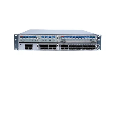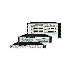
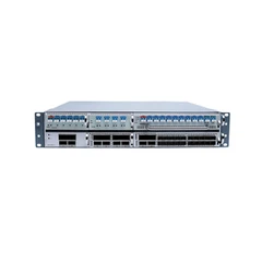

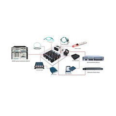


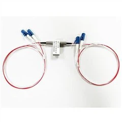
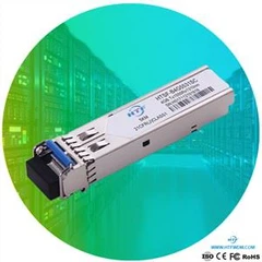


Arrayed waveguide grating (AWG) is based on the basic optical principle of linear interference between different wavelengths of light, which means that if each channel uses light with different microwave length, many channels of light can be carried by a single fiber, and there is only negligible signal crosstalk. Arrayed waveguide grating (AWG) can combine the light of multiple channels into a single fiber at the transmitting end, and separate the light again at the receiving end.
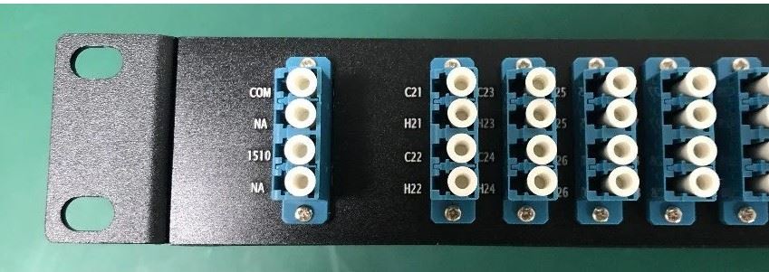
Features
Low Insertion Loss
Established silica-on-silicon
Low PDL
Low chromatic dispersion
Telcordia GR-1221-CORE qualified
Applications
DWDM transmission
Wavelength Routing
Optical add/drop multiplexing
Arrayed waveguide grating (AWG) is the preferred technology in the rapidly developing dense wavelength division multiplexing (DWDM) network. AWG has the characteristics of filtering and multi-function. It can obtain a large number of wavelengths and channels, and realize the multiplexing and demultiplexing of tens to hundreds of wavelengths. By using the matrix form of n × n, n different optical signals can be transmitted at n wavelengths at the same time, and multi-functional devices and modules can be formed flexibly with other optical devices. In addition, AWG also has high stability and good cost performance, which is very suitable for DWDM systems with high speed and large capacity. AWG device is a planar waveguide device based on optical integration technology. It has the potential advantages of planar waveguide technology. It is suitable for mass production with good repeatability, small size, good uniformity of insertion loss, good thermal stability after temperature control, and can be integrated with active devices to form optoelectronic integrated circuit (OEIC). It is the mainstream technology of optical communication in the future.
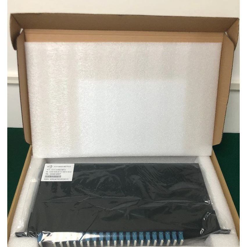
The standard AWG consists of five parts: input waveguide, input star coupler, array waveguide, output star coupler and output waveguide.
The principle of arrayed waveguide grating is: after the multiplexed signal light with multiple wavelengths is output through the waveguide of central input channel, it diffracts in the input plate waveguide, reaches the input concave grating for power distribution, and couples into the arrayed waveguide region. Because the end face of the arrayed waveguide is located on the circumference of the grating circle, the diffracted light reaches the end face of the arrayed waveguide with the same phase. After transmission through the arrayed waveguide, because the adjacent arrayed waveguides maintain the same length difference Δ L, the output light of a certain wavelength of adjacent array waveguides on the output concave grating has the same phase difference. For the light of different wavelengths, the phase difference is different, so the light of different wavelengths diffracts in the output planar waveguide and focuses on different waveguide positions of the output channel After the output of the channel waveguide, the wavelength assignment or demultiplexing function is completed. The reverse process of this process, that is, if the signal light is input reversely, the multiplexing function is completed, and the principle is the same.
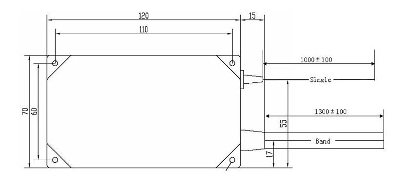
Specifications
parameter Number of channels | Specifications | |
Min | Max | |
Channel spacing | 40 | |
Central wavelength | 100 GHz | |
Passband frequency | C -band nm | |
Wavelength accuracy | ±0.1 nm | |
0.5 dB bandwidth | ±0.05 nm | |
1 dB bandwidth | 0.2 nm | |
3 dB bandwidth | 0.4 nm | |
20 dB bandwidth | 0.6 nm | |
Insertion loss | 1.2 nm | |
Isolation of adjacent channels | 6 dB | |
Isolation of non adjacent channels | 25 dB | |
Total crosstalk | 30 dB | |
Insertion loss consistency | 22 dB | |
Flatness of insertion loss | 1.2 dB | |
Return loss | 0.5 dB | |
Polarization dependent loss | 40 dB | |
Polarization mode dispersion | 0.5 dB | |
Maximum carrying optical power | 0.5 ps | |
Optical power monitoring range | 24 dBm | |
parameter | -35 dBm | +23 dBm |
Environmental Conditions
Parameters | Notes | Specifications | Units | ||
Min | Typ | Max | |||
Operating Temperature | -5 | +65 | °C | ||
Storage Temperature | -40 | +85 | °C | ||
Relative Humidity | 0 | 90 | % | ||
Ordering Information
AWG | X | XX | X | XXX | X | X | X | XX |
Band | Number of Channels |
Spacing |
1st Channel |
Filter Shape |
Package |
Fiber Length |
In/Out Connector | |
C=C-Band L=L-Band D=C+L-Band X=Special | 16=16-CH 32=32-CH 40=40-CH 48=48-CH XX=Special | 1=100G 2=200G 5=50G X=Special | C60=C60 H59=H59 C59=C59 H58=H58 XXX=special | G=Gaussian B=Broad Gaussiar F=Flat Top | M=Module R=Rack X=Special | 1=0.5m 2=1m 3=1.5m 4=2m 5=2.5m 6=3m S=Specify | 0=None 1=FC/APC 2=FC/PC 3=SC/APC 4=SC/PC 5=LC/APC 6=LC/PC 7=ST/UPC S=Specify |
Main applications
(1) Wavelength routing: when the optical signal passes through the network node, the route is selected according to its wavelength, without photoelectric conversion. The wavelength determines the path of optical signal transmission, realizes wavelength reuse and improves the wavelength utilization.
(2) Led spectrum division multi wavelength light source: using arrayed waveguide grating (AWG) to segment the wide spectrum light of LED, a low-cost multi wavelength light source can be obtained for WDM-PON (wavelength division multiplexing passive optical network)
(3) Optical add / drop multiplexer: at the node of optical signal network, it is often necessary to "divide" part of signal flow from node, or "plug" some signal flow into network transmission system. This kind of device which can separate and insert the signal is called "optical add drop multiplexer".
(4) Optical cross interconnection: the optical cross interconnection device is mainly used to complete the cross connection between multi wavelength ring networks. As the node of the grid optical network, the purpose is to realize the automatic configuration, protection, recovery and reconstruction of the optical wave network.
(5) All optical transmission network: in all-optical network structure and all-optical transmission network, OXC and OADM play the role of information transmission and cross interconnection.
If you need anything, you can contact HTF Zoey.
contact:support@htfuture.com
Skype:sales5_ 1909,WeChat:16635025029